


Surface finishing with abrasive brushes is a wide and extensive branch of the general surface finishing. H. Günther Falkenrich GmbH offers the broadest product range in its industry. With some 3,500 variants, regardless of the dimensions, we offer for almost every application the perfect tool. In addition to the theoretical advice from our team of experts in the sales meeting, we offer free practical processing of your samples in our house. Our company's own laboratory provides grinding test with his hands-on equipment. We are capable of applying all possible methods for the perfect use of the products prior to integration into your existing processes. This accelerates the product determination and does not interrupt your own production. Should our machines not be sufficient for your requirements, additional testing will be conducted in the industry. We are also cooperating with machine manufacturers and users.
Test Laboratory - Demonstration and Testing
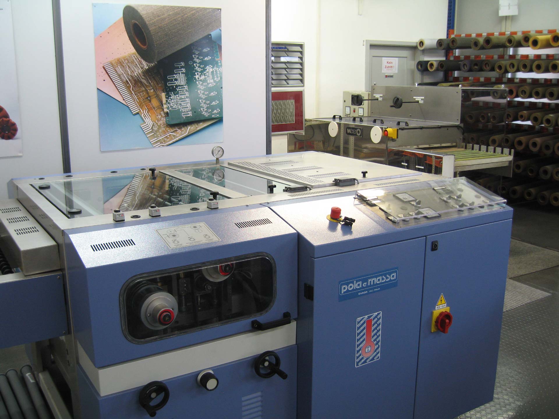
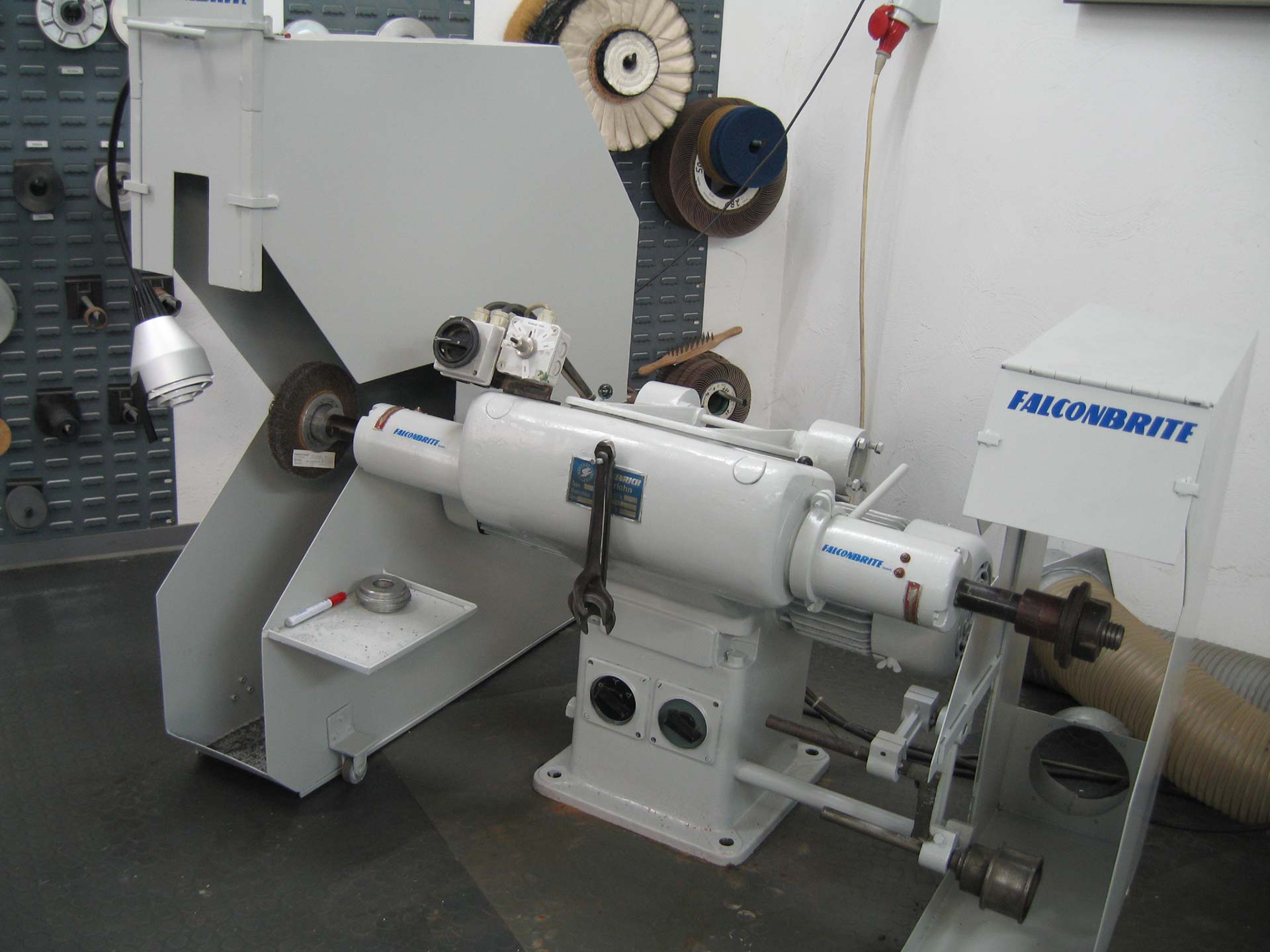
With our machinery we are able to perform the following processes in our house:
- Matting and Glazing of metals and other materials
- Deburring and cleaning of flat parts
- Processing of internal parts
- Preparation of technical and decorative surfaces
- Removal of surface layers and
- Roughening of surfaces
- Processing of printed circuit boards (PCBs) and press plates
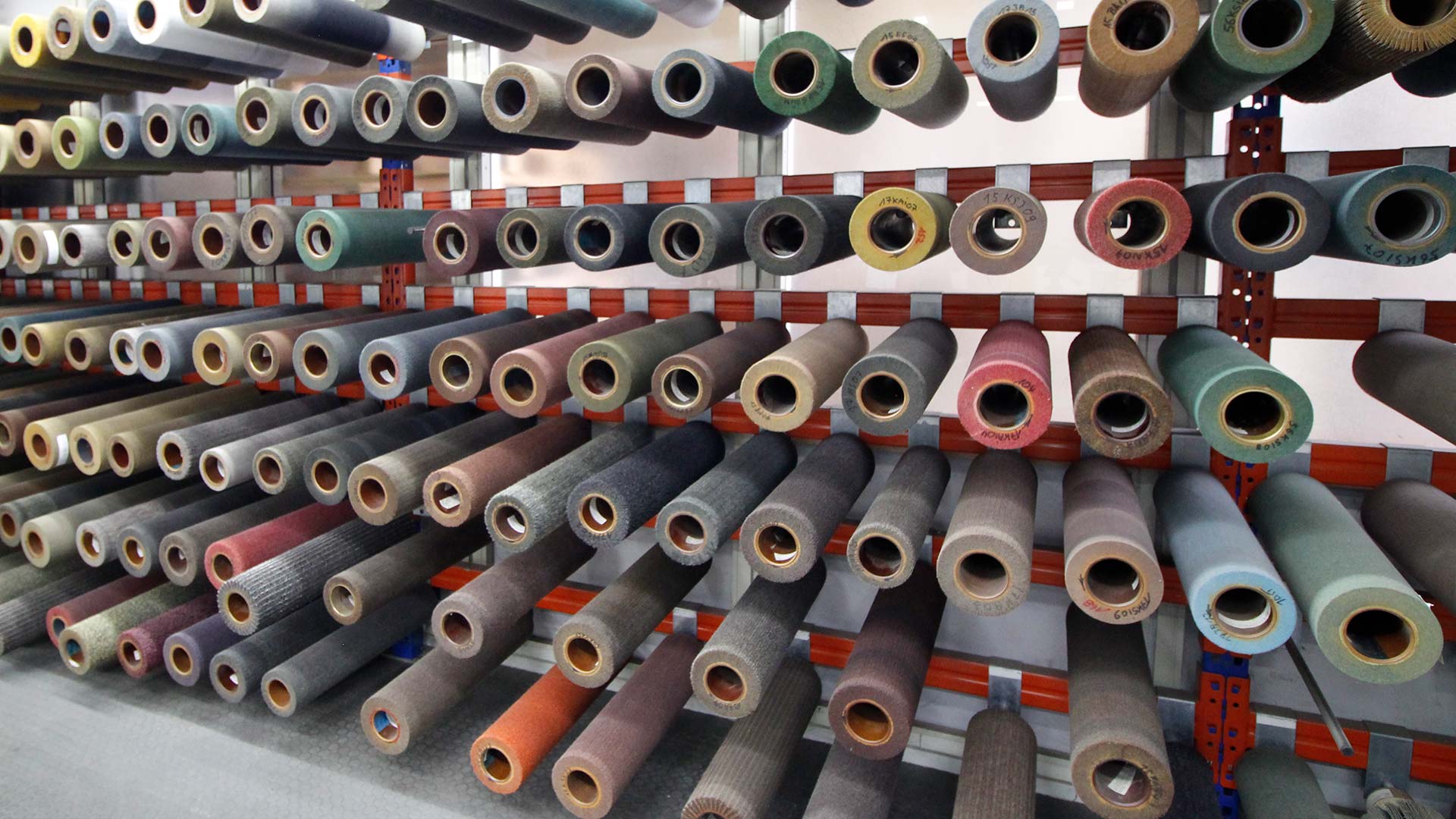
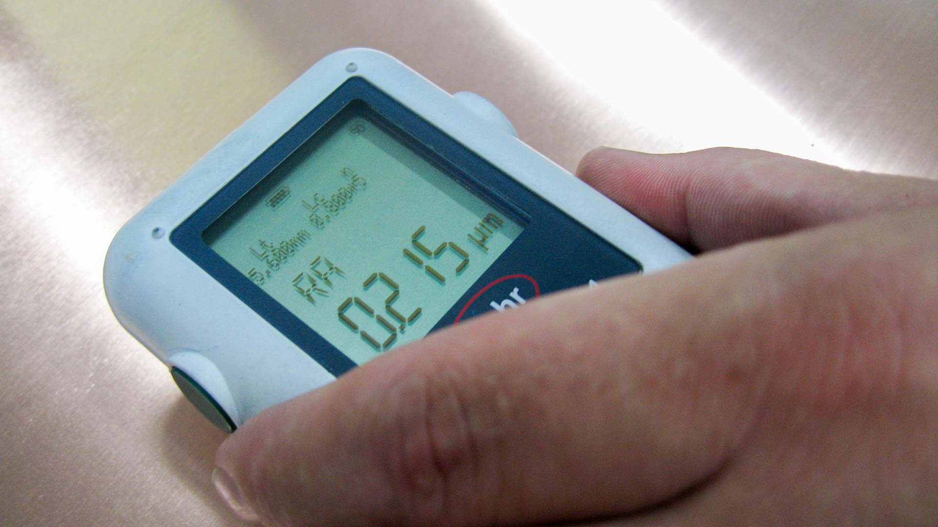
Working together with our customers, these applications can be implemented in throughfeed or for single part machining, as well as in wet or dry processes. More than 250 different brush types with grain sizes from 36 to 2,000 are available for test applications. Furthermore, we also produce individual brushes according to the customer’s specifications on short notice. The state-of-the-art laboratory has roughness meters, microscopes, reflection meters and coating thickness gauges, among other things.
To ensure perfect quality of service you will be supported in commercial and technical application questions by one of our qualified engineers and technicians as a contact.
-
arrow_drop_downGeneral Technical Information about non-woven Materials
Working Speed
When selecting the working speed for non-woven material products it is most important to consider two different criteria:
- The maximum speed provides a sufficient degree of safety, and stays within the physical limitations of the relevant tool construction.
- The functional speed corresponds with the working speed in order to achieve the required results.
The following recommended peripheral speeds have been established in numerous tests. These tests have clearly indicated that the functional speed for our products is lower than the stated maximum speed. Subsequently, the stated maximum operating speed should not be exceeded, not even for test purposes. The best setting for an optimum functional speed can often only be determined after briefly testing the chosen tool on the relevant work piece, particularly if it is important to improve the visual appearance of the work piece.
Advice
- The lower the working speed, the longer the life span of the tool.
- The higher the working speed, the greater the grinding effect, the shorter the life span of the tool.
Falkenrich-Product Material Recommended working speed / peripheral speed Non-woven flap wheel
(not impregnated)Wood
Steel
Stainless steel
Non-ferrous metals10 - 12 m/s
12 - 20 m/s
10 - 15 m/s
7 - 15 m/sNon-woven flap wheel
Non-woven convoluted wheelSteel
Non-ferrous metals
Plastic17 - 24 m/s
10 - 28 m/s
12 - 18 m/sConveyor Speed
The feed rate determines the speed at which the work piece is conveyed past the tool. It is expressed in meters per minute (m/min). The 'process time' is dependant on the feed rate. The process time is the time during which the work piece is in contact with the tool.
The longer the process time, the greater the grinding effect.Direction of Feed
The work piece can be conveyed in the direction of rotation or vice versa. If the tool moves in the opposite direction to the work piece, the relative process time is longer and therefore the grinding effect on the material is greater. Therefore, if the line pattern is shorter a greater cutting depth is effected. If the tool moves with the direction of the work piece, the process time is shorter, hence a regular finish is created with a longer line pattern.
Applied Pressure
The grinding effect can be influenced by applying different pressures:
- Longer process time
- Better cutting performance
- Faster machining
Advice
- Higher pressure provides higher grinding effect.
- Lower pressure provides lower grinding effect.
- oo much pressure can cause smearing of the non-woven material products.
Cutting speed as a function of rotational speed (rpm) and diameter:
General formula: [AD-Ø (mm) x 3,1416 x U/min] / 60.000 = m/s -
Nature of fault Cause of fault - machine Cause of fault - roller brush Remedy of fault The markings are running diagonally to the running direction Damaged bearings
Jamming of the work piece feedUnbalanced rollers through incorrect operation Maintenance of the brushing machine
Take off the brush and/or send it off for strip threadingThe panels are only brushed on one side in the direction of the feed The roller brush is not aligned parallel to the counter pressure roller The roller brushes are possibly not round or conical Take off the brush and/or send it off for strip threading Longitudinal lines on the PCB's Faulty rinsing unit
The conveyor and/or counter pressure rolls are dirtyThe roller brushes are blocked with residues
Damaged roller surfaceRepair the rinsing unit, if necessary get it serviced and properly adjusted
Clean the machine
Send off the rollers for strip threading or remove them
Adjust the oscillationThe boards are only brushed in parts Incorrect contact pressure The brushes are too hard Adjust the contact pressure
Select appropriate brushesThe burr was not removed Incorrect contact pressure
Incorrect feed
Incorrect rotation direction of the brushesThe brushes are too soft
Incorrect abrasionSelect appropriate brushes
Adjust the abrasion
Adjust the rotation direction
Adjust the feed
Adjust the contact pressureThe burr partially comes to a halt Rinsing unit is not correctly adjusted The brush is blocked Take off the brush or send it off for strip threading The burr is pressed into the bore / secondary burring The rinsing unit is not correctly adjusted
Incorrect contact pressure
Feed too fastBlocked brush
The brush is too softRepair the rinsing unit and adjust properly
Adjust the contact pressure
Adjust the feed
Take off the brush and/or send it off for strip threading
Select the appropriate brushThe drill hole edge is very rounded Incorrect contact pressure
Feed too slowThe brush is too soft
Incorrect abrasionAdjust the contact pressure
Adjust the feed
Select the appropriate brushThe drill hole is ovalised See above See above See above Problems with the adhesion
undercutThe rinsing unit is incorrectly adjusted or damaged Incorrect abrasion Select the correct abrasion Blocked bores The rinsing unit is incorrectly adjusted or damaged
Defect filtration
Poor water qualityHigh brush grinding effect
Loosened particles are too big
Irregular grinding effectRepair the rinsing unit and the filtration and adjust properly
Use filtered water
Select the appropriate brush à Falke long life-DEBU-impregnation
Have the step turnedThin inside layer
Bending of edgesIncorrect contact pressure
Incorrect rotation direction of the rollersThe brush is too hard Select the appropriate brush
Adjust the rotation direction
Adjust the contact pressureDamaged multi layers
Only partial brushing of the surfaceIncorrect pressure
Incorrect feedThe brush is too hard Select the appropriate brush
Adjust the contact pressure
Adjust the feedThe press panels are not properly cleaned The rinsing unit is incorrectly adjusted or damaged The brush is blocked or full of glass Select the appropriate brush
Take off the brush and/or send it off for strip threading
Brushes with recessed edges have the following advantages:
- No damaging of the billy rolls
- 100 % transferring of brush pressure on the PCBs
- Avoiding of residues from the board
- Indicated by a "T + mm" in the product designation, e.g. 23 MS 07 T 15

We recommend following adjustment of your water supply in your brushing machine:

-

Please wear suitable hearing protection!

Please wear suitable eye protection glasses!

Please wear suitable gloves!

Please wear a suitable dust mask!
When using our products by machine, please follow the technical instructions and instructions of the machine manufacturer!
-
arrow_drop_downPress Panel Cleaning
Assembly instructions for roller brushes for press panel cleaning
- Place the roller brush on the 'Wesero' assembly carriage and fold down the brush shaft supports.
- Guide the brush shaft into the bore (inner diameter = 190mm) of the roller brush. Take care not to damage the balancing threads situated inside the roller.
- Push all the required adapters onto the brush shaft, taking care to ensure they are not pushed into the bore of the roller brush.
- Lift the roller brush on one side and fold up the shaft support. Secure the support with the screw provided.
- The roller brush and the brush shaft are now positioned concentrically to each other. Now, one by one, push all the adapters into the bore of the roller brush. Do not use hammers or excessive force to position the adapters!
Some more advice
The balancing weights are adhered in the laminated paper tube. Take care that these weights are not damaged or removed on installation of the shaft. Insert the aluminium flange with a separating agent (e.g. Lithium soap fat). Ensure that the driving pin is positioned correctly. Any jamming of the flange can cause the roller to break. We recommend 17m per second as an ideal operating speed for new rollers; if the rollers are almost worn we recommend a speed of approx. 14 m per second. The rotation direction of the roller is marked by an arrow on the side. The water pressure for your brushing machine should be in the region of 3 bar.
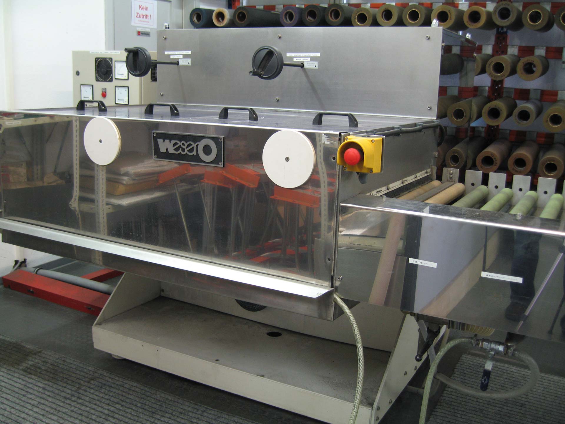
Adjusting the roller brushes of the 'WESERO' for wet operation
- Switch off the machine and open the lid.
- Switch the machine to manual operation and turn the roller brushes down (release the contact pressure) to a point where they can be turned by hand.
- Prior to levelling, the brushes must be thoroughly spinned without water being added by turning them for about 15 to 20 minutes.
- Check the roller surface and the roller heads for any exterior damage. If the roller heads are protruding they should be levelled with a right angle grinder prior to use. Note: the roller body must only be turned by hand.
- Separate the brushes further after the heads have been levelled and switch on the brushes that still need to be levelled with oscillation.
- Insert the adjusting plate into the machine to a point where the plate of the conveyor roller will be gripped in front and behind the brushes, which are to be adjusted.
- Now switch on the brush and adjust to a point where the operating level indicates 30% - 35%. Then the feed must be switched on and off in short intervals of approx. 5 seconds. (Caution! - Longer process times will destroy the brush and the adjusting plate!). Ensure that the capacity intake is always between 30% -35%, if necessary, adjust via the in-feed. This procedure must be repeated three to four times.
- The same procedure applies to the following brushes. Ensure that only the brush that is to be treated is switched on during the complete levelling process.
- When the levelling process has been completed, the adjusting plate must be retracted, to avoid any soiling of the conveyor rollers inside the dryer. Clean the engine compartment with water afterwards.
- Ensure that the jets are clean and the jet beam pints in the direction as specified in the manual, before the machine is operated again.
Adjusting the roller brushes of the ' WESERO' brushing machine for dry operation
- Switch off the machine, open the lid and take out the suction trough.
- Switch the machine to manual operation and turn down the roller brushes (release the contact pressure) until they can be turned by hand.
- Check the roller surface and the roller heads for exterior damage. If the roller heads are protruding they should be levelled with a right angle grinder prior to use. Note! The roller body must only be turned by hand.
- Install the suction trough and switch on the duster.
- Separate the brushes further after the heads have been levelled and switch on the brushes, that still need to be levelled with oscillation.
- Insert the adjusting plate into the machine to a point where the plate of the conveyor roller will be gripped in front and behind the brushes, which are to be adjusted.
- Now switch on the brush and adjust to a point where the operating level indicates 30% - 35%. Then the feed must be switched on and off in short intervals of approx. 5 seconds. (Caution! -Longer process times will destroy the brush and the adjusting plate!). Ensure that the capacity intake is always between 30% -35%, if necessary, adjust via the in-feed This procedure must be repeated three to four times.
- The same procedure applies to the following brushes. Ensure that only the brush that is to be treated is switches on and the suction device is switches on during the complete levelling process.
- When the levelling process has been completed, ensure you clean the machine thoroughly and hoover the brush surface.